I. Introduction
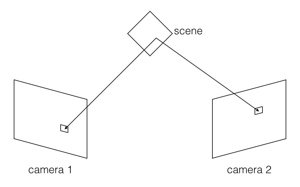
An object may look different from different viewpoints. For example, a cube may look like a square from some viewpoints, but may look like a hexagon containing 3 parallelograms, each representing one face of the cube, from others. The difference between two viewpoints can be used to calculate the 3D model of the object; we call such a technique 3D reconstruction. The accuracy of the reconstructed 3D model directly depends on the accuracy of the two-view correspondence, which is the mapping between the positions of the same 3D points imaged in the two viewpoints. The most common correspondence is between two cameras, where each camera represents one of the viewpoints.
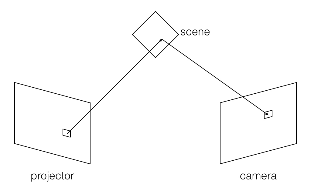
However, as the path of light is reversible, we can replace one of the cameras with a projector to find the correspondence. Here, the correspondence is defined as the mapping from the pixels of the camera sensor to the pixels of the projector sensor, where the pixel in the camera is directly illuminated by the corresponding pixel in the projector. The light goes from the projector, hits the scene, and then gets reflected directly to the camera without any other reflections in the scene. Note that the correspondence is dependent on the scene.
II. Structured Light for Acquiring Correspondence
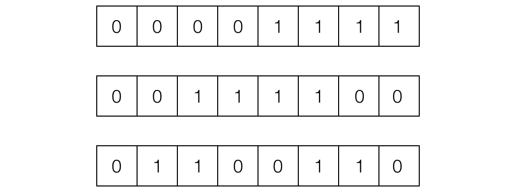
The simplest way to reconstruct a 3D model is to turn on only one pixel in the projector at a time, and record the corresponding pixel in the camera, but this method is very inefficient. Our method is to assign every pixel in the projector a unique code consisting of 0’s and 1’s. As proposed by Scharstein et al. in 2003, using grey code to represent the x and y coordinates is a desirable solution. Then, we must project the code in multiple images, as shown in Figure 2. By capturing the code and decoding the pictures, the corresponding pixels on the projector can be found, and the needed correspondence can be acquired. Compared with the method of turning on only one pixel at a time, the complexity was reduced from \(\mathcal{O}(n)\) to \(\mathcal{O}(\log{n})\), where n is the resolution of the projector.
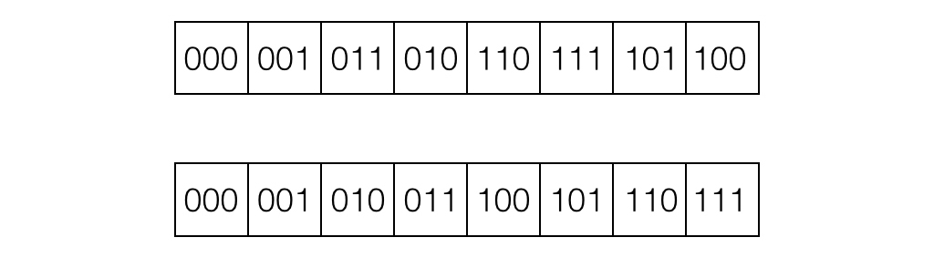
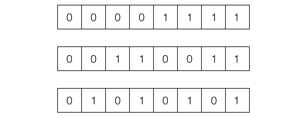
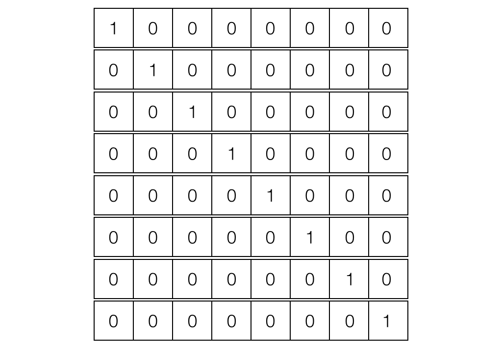
Apart from using grey code, we also tried two other methods. One was replacing grey code with binary code, which produced very noisy correspondence, therefore making it very inaccurate. The other was to project 1-pixel wide horizontal or vertical lines, one line at a time. The idea is similar to turning on only one point at a time, but we used the lines to get the row index and column index. This second approach produces results as accurate as what we achieved with grey code, but it is much less efficient as its runtime is \(\mathcal{O}(\sqrt{n})\). In practice, using grey code only costs 5 minutes or less, but using strips needs approximately 2 hours, where the projector we use has resolution \(684 \times 608\).
III. Indirect-Invariant Imaging
In our previous method, we implicitly assumed that the light only travels through the direct paths, i.e. all light goes from the projector to the camera by bouncing off the scene at most once [O’Toole et al. (2014)]. However, this assumption does not hold in many cases, especially in scenes with specular surfaces, like mirrors, or scenes with transparent or semi-transparent objects, like candles. In these complex scenes, light could get reflected between objects or inside some objects. We define the light in the assumption as direct light, and the rest as indirect light.
However, for any point in the projector, its corresponding point must lie on a straight line in the camera called the epipolar line, which can be calculated from the relative position of the camera and the projector, regardless of the scene. Additionally, the points in the projector corresponding to the same epipolar line lie on a straight line, which is another epipolar line. Thus, points on the epipolar line in the projector will get mapped to points on the corresponding epipolar line in the camera. This property is known as epipolar constraint.
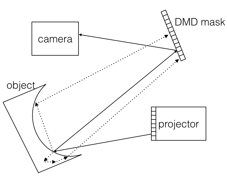
According to epipolar constraint, if only one epipolar line in the projector is turned on, and only the light on the corresponding epipolar line is captured by the camera, we can get the image with almost nothing but direct light on the epipolar line, as the randomness of indirect light makes it unlikely to fall on the epipolar line. We used a primal-dual coded camera [O’Toole et al. (2012)], which consists of a projector and a programmable mask in front of the camera, to project patterns and control which pixels can be captured in the camera. But we designed light-efficient patterns for the projector and the mask, rather than projecting only one epipolar line each time.
IV. Future Work
We are going to combine the two techniques above so that we can capture an indirect-invariance image, or direct-light-only image. We can ignore the small portion of indirect light which also travels between corresponding epipolar lines when using structured light to acquire correspondence between the projector and the camera. As a result, we expect to get more accurate correspondence, especially in scenes with specular and inner reflection.
References
[1] M. O’Toole, J. Mather, and K. Kutulakos, ‘3D Shape and Indirect Appearance By Structured Light Transport’, in Proc. of CVPR, pp. 3246-3253, 2014.
[2] M. O’Toole, R. Raskar and K. Kutulakos, ‘Primal-dual coding to probe light transport’, TOG, vol. 31, no. 4, pp. 1-11, 2012.
[3] D. Scharstein and R. Szeliski, ‘High-Accuracy Stereo Depth Maps Using Structured Light’, in Proc. of CVPR, pp. 1-195, 2003.